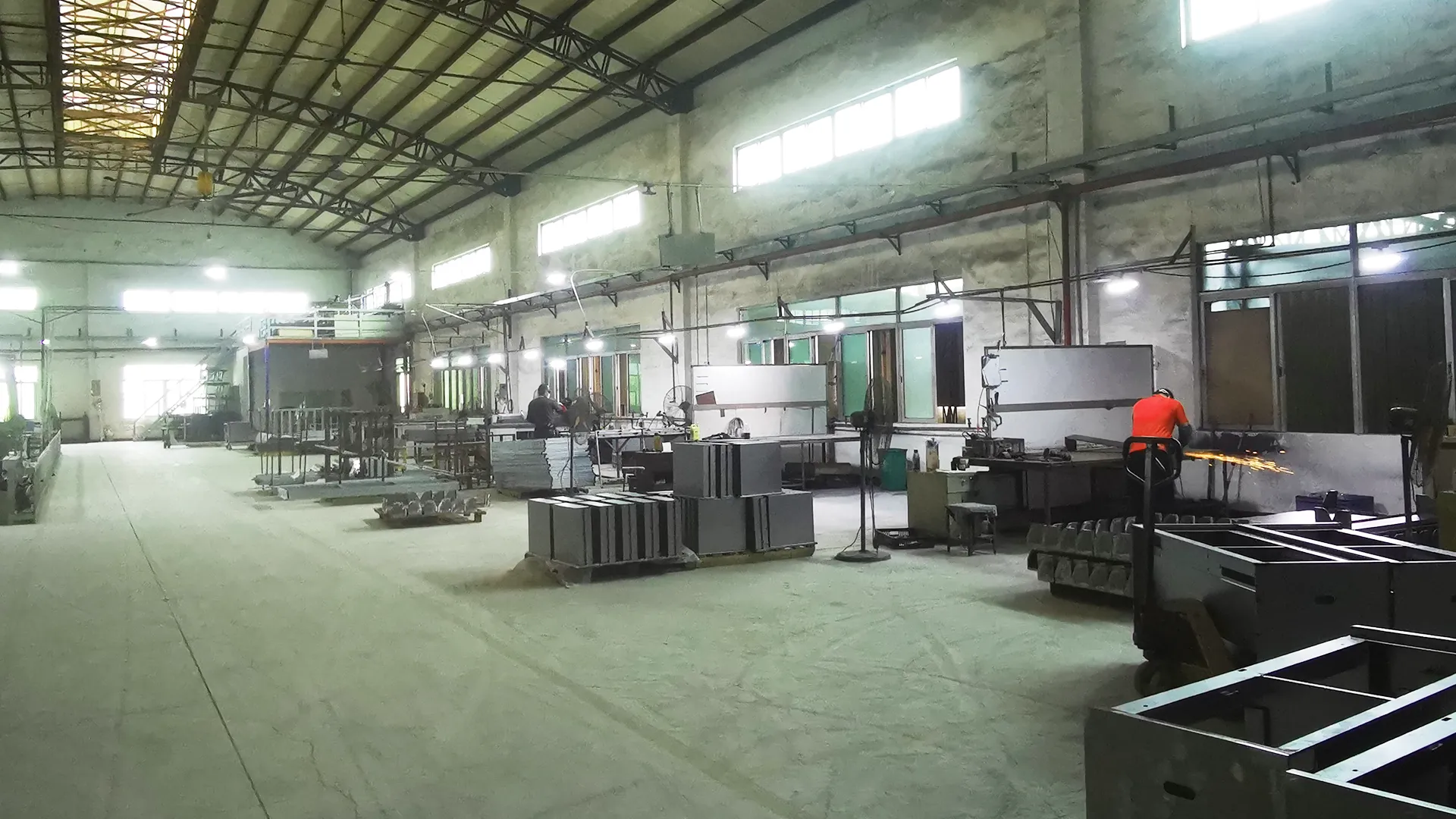
Fabex engineer reviewing fabricated sheet metal parts for manufacturability

CAD-to-production engineering review

Sheet Metal Design for Manufacturability

Turn functional CAD into a practical cutting, bending, welding and finishing route. Fabex reviews manufacturing risk, cost drivers and missing drawing details before production.

Review Design Rules
Manufacturing routeCutting through finishing
Drawing clarityDatums, tolerances and interfaces
Cost controlTooling, setups and material use
Production releaseOpen risks documented first

The bridge between CAD and the shop floor

Resolve manufacturing risk while changes are still inexpensive

A CAD model can be geometrically valid and still require fragile tooling, inaccessible bends, manual alignment, excessive welding or unrealistic inspection. Those decisions appear later as scrap, rework, added fixtures and schedule risk.

Fabex DFM connects the design to available material, cutting method, bend tooling, assembly sequence, finish system and inspection plan. The result is a documented set of questions and proposed changes for customer approval, not an automatic redesign of functional requirements.

All dimensions on this page are initial review guidelines. Project-specific limits are confirmed against the material, tooling, geometry, process and required result.

Dimension the manufacturing risk

Four rules engineers can check in CAD

The diagrams define what each distance means. Use them to screen a design, then confirm the final limit during Fabex review.

Hole spacing and edge distance diagram A sheet edge with two holes showing clear edge distance, clear web spacing and hole diameter. e >= 1.5t web >= 2t D Punching starting rules; laser limits depend on cut quality and material

Protect the material around holes

For punching, clear edge and web distances help prevent bulging, tearing and weak ligaments. Laser-cut limits can be smaller, but edge quality and heat input still need review.
Hole to bend distance diagram A sheet metal flat pattern showing clear distance from the hole to the part edge and from the hole edge to the bend tangent. bend clearance >= R + 2t edge >= 1.5t bend tangent bend zone Measure both clearances from the hole edge

Measure from the bend tangent

A hole needs clearance from both the outside part edge and the bend zone. Use a clear hole-to-edge distance of at least 1.5t as an initial rule, and measure bend clearance from the hole edge to the bend tangent, not from the hole centre.

Coating buildup on a hole diagram A section through a coated hole showing coating thickness reducing the finished opening on both sides. D raw D finished c D finished approximately equals D raw - 2c

Reserve space for the finish

Powder builds on both sides of an opening. Fits, slots, hinge features and threaded areas should be sized or masked for the specified coating system.

Rolling grain and bend direction diagram A sheet showing the preferred bend line perpendicular to the rolling direction. bend line rolling direction 90 degrees preferred

Orient critical bends across the grain

Where sheet rolling direction is known, critical bend lines generally run perpendicular to it. Material grade, temper, radius and bend angle still govern crack risk.

Flat-pattern reference

Use formulas with real tooling data

Define t as sheet thickness, R as inside bend radius, V as die opening, theta as bend angle in radians, K as the neutral-axis factor and c as coating build per surface.

Hole edge to bend tangent

e >= R + 2t

Initial review rule. Increase clearance for severe bends, sensitive materials or critical hole shape.

Minimum flange estimate

Lmin ~= V/2 + R

A tooling-based estimate. A common air-bend V-opening is about 6t to 10t, subject to the material and process.

Bend allowance

BA = theta(rad) x (R + Kt)

K is the neutral-axis factor. Use the fabricator bend table or test data for released flat patterns.

Outside setback

OSSB = tan(theta/2) x (R + t)

Applies to the included geometry convention used for the calculation; keep drawing conventions consistent.

Bend deduction

BD = 2 x OSSB - BA

Flat length equals the sum of outside flange dimensions minus the bend deduction.

Powder-coated opening

Dfinished ~= Draw - 2c

Typical powder build c is about 0.06-0.12 mm per surface. Anodizing requires a separate allowance model.

Complete-part review

DFM checklist by manufacturing process

A change that helps one operation can create a problem downstream. Review the complete route before releasing geometry.

01

Laser cutting and punching

Select rules by process rather than applying one minimum to every cut feature.

  • For punched mild-steel holes, D >= t is a practical starting point; for stainless steel, prefer D >= 1.5t.
  • For punching, begin with clear hole-to-edge distance >= 1.5t and clear hole-to-hole web >= 2t.
  • For laser cutting, confirm small holes, narrow slots and closely spaced cuts against material, thickness and required edge quality.
  • Use standard feature sizes and uncomplicated outlines where function permits to support tooling reuse and efficient nesting.
02

Bending and forming

Design around real press-brake tooling, access and springback rather than nominal CAD geometry alone.

  • Keep inside bend radii consistent where possible; R near t is a common starting point, not a universal minimum.
  • Estimate minimum internal flange length from Lmin ~= V/2 + R, then confirm the selected punch, V-die and bend sequence.
  • Use bend relief width >= t or 1.5 mm, whichever is practical, and extend the relief beyond the bend tangent.
  • Avoid trapped bends and reverse forms that block tool access or require unnecessary reorientation and special tooling.
03

Stiffness without excess thickness

Geometry can add stiffness with less weight and material than simply increasing the sheet gauge.

  • Use return flanges, hems, ribs, beads or cross-breaks to control flex and oil-canning in large panels.
  • Keep formed details away from edges, bends and each other so the tooling can seat and material can flow.
  • Review hem radius, material temper and rolling direction to reduce cracking on folded edges.
  • Treat large welded or coated panels as distortion-sensitive and plan restraint, sequence and acceptance criteria.
04

Welding, hardware and assembly

Every joint must locate reliably and leave physical access for the production tool.

  • Use tabs and slots where appropriate to self-locate welded subassemblies and reduce fixture dependence.
  • Provide flat seating clearance for self-clinching hardware and keep insertion tooling clear of bends and edges.
  • Check direct access for weld torches, spot-weld tips, riveters, torque tools, clamps and inspection gauges.
  • Design joints and weld sequences to balance heat input around critical dimensions and cosmetic faces.
05

Tolerances and inspection

Tolerance should communicate function and inspection intent. Process, material, thickness, feature relationship, part size and assembly sequence determine what is practical.

  • Identify functional datums, mating interfaces and truly critical characteristics on the drawing.
  • As review starting points, suitable CNC-machined features may achieve +/-0.05 to +/-0.10 mm, while laser-cut features commonly use about +/-0.2 to +/-0.5 mm depending on material, thickness, size and edge requirement.
  • Fabricated sheet-metal assembly interfaces often use about +/-0.5 to +/-1.0 mm in practice; part size, bend stack-up, weld distortion, fixtures, coating and the measurement datum can require a different value.
  • Avoid blanket tight tolerances. Reserve them for function, fit or safety because extra setups, machining, fixtures and inspection increase cost and lead time, and some requirements are impossible for the selected route.
06

Surface treatment and corrosion

Specify the substrate, environment and complete finish system before geometry is frozen.

  • Allow coating buildup on slip fits, slots, hinges and external mating features; mask threads, contacts and gasket lands where required.
  • Include hanging and drainage features for plating, e-coating and wet processes, and remove sealed pockets or liquid traps.
  • Round or break sharp edges where coating coverage and outdoor corrosion performance matter.
  • Review cut edges, welds, galvanic pairs and water paths as part of the complete corrosion system.
07

Stock size, shipping modules and logistics

Design the shipping pieces around material utilization and the real transport route, not only the final assembled envelope.

  • Use standard 2440 x 1220 mm sheet stock efficiently where the design permits; oversize sheet usually adds sourcing time, material cost and waste.
  • One standalone part can be reviewed up to 5 m long x 3 m wide x 3 m high, but this is not a routine shipping envelope.
  • Target shipping pieces at approximately 2.3 m or less in the relevant dimension where practical, leaving room for pallets, crates, protection and loading clearance.
  • Split very large assemblies into transportable modules with defined datums, joints, fasteners, lifting points and site-assembly access; verify the packed size against the selected container, truck and route before release.

Useful input, useful review

What to send with your RFQ

A clean data package lets the review focus on production decisions instead of chasing missing requirements. Mark any feature that cannot be changed.

  1. 01 3D model in STEP format when available
  2. 02 Dimensioned drawing with datums and critical tolerances
  3. 03 Material grade, temper and sheet thickness
  4. 04 Prototype, annual and order quantities
  5. 05 Finish system, colour, gloss and cosmetic faces
  6. 06 Mating parts and assembly or installation orientation
  7. 07 Indoor, outdoor, coastal or chemical exposure
  8. 08 Inspection reports, certificates or test standards required

Engineering questions

Sheet metal DFM FAQs

Are these DFM formulas guaranteed manufacturing limits?

No. They are screening rules that help identify risk early. Final limits depend on material grade and temper, thickness, grain direction, part geometry, tooling, process route, finish and inspection requirement. Fabex confirms the applicable limits during drawing review.

Should I send a finished flat pattern?

Send the formed 3D model and dimensioned drawing whenever possible. A customer flat pattern is useful as a reference, but the released blank should use Fabex tooling data, bend deductions and manufacturing sequence unless otherwise agreed.

Can Fabex suggest lower-cost design changes?

Yes. Typical opportunities include standardizing radii and hardware, relaxing non-critical tolerances, improving tool access, simplifying welds, changing the part split, selecting available material and matching the finish to the actual environment.

Does a DFM review replace engineering validation?

No. DFM evaluates manufacturing practicality and production risk. The customer remains responsible for product function, loads, safety, compliance and application validation unless a separate engineering scope is agreed.

What information produces the most useful review?

Provide a STEP model, controlled drawing, material and finish specifications, quantities, critical interfaces, assembly context and intended environment. Mark the dimensions or surfaces that cannot change.

Why should I not apply the tightest available tolerance to every dimension?

The tightest achievable value on one CNC-machined feature is not a realistic default for laser-cut, bent, welded, coated or large assembly dimensions. Start from function, fit, safety and measurement intent, then assign a practical tolerance for each process and feature relationship. Unnecessary precision adds setups, secondary machining, fixtures, inspection, rework risk, cost and lead time, and some requirements are impossible for the selected route.

Review the drawing before the first part is cut

Send your CAD, drawing, material, finish and quantities. Fabex will identify manufacturing questions and propose practical changes for your approval.

Email the Engineering Team