Sheet Metal Bend Allowance & K-Factor: How to Calculate the Right Flat Blank
Sheet Metal Bend Allowance & K-Factor: How to Calculate the Right Flat Blank
If you have ever bent a sheet metal part and found the flat blank came out short or long, the problem usually isn’t your operator — it’s the bend allowance. This is one of the most misunderstood parts of sheet metal design, and it is the single most common reason parts don’t fit on the first try.
This guide explains bend allowance and K-factor in plain language, with formulas you can actually use, so you stop guessing and start getting parts right the first time.
The core problem
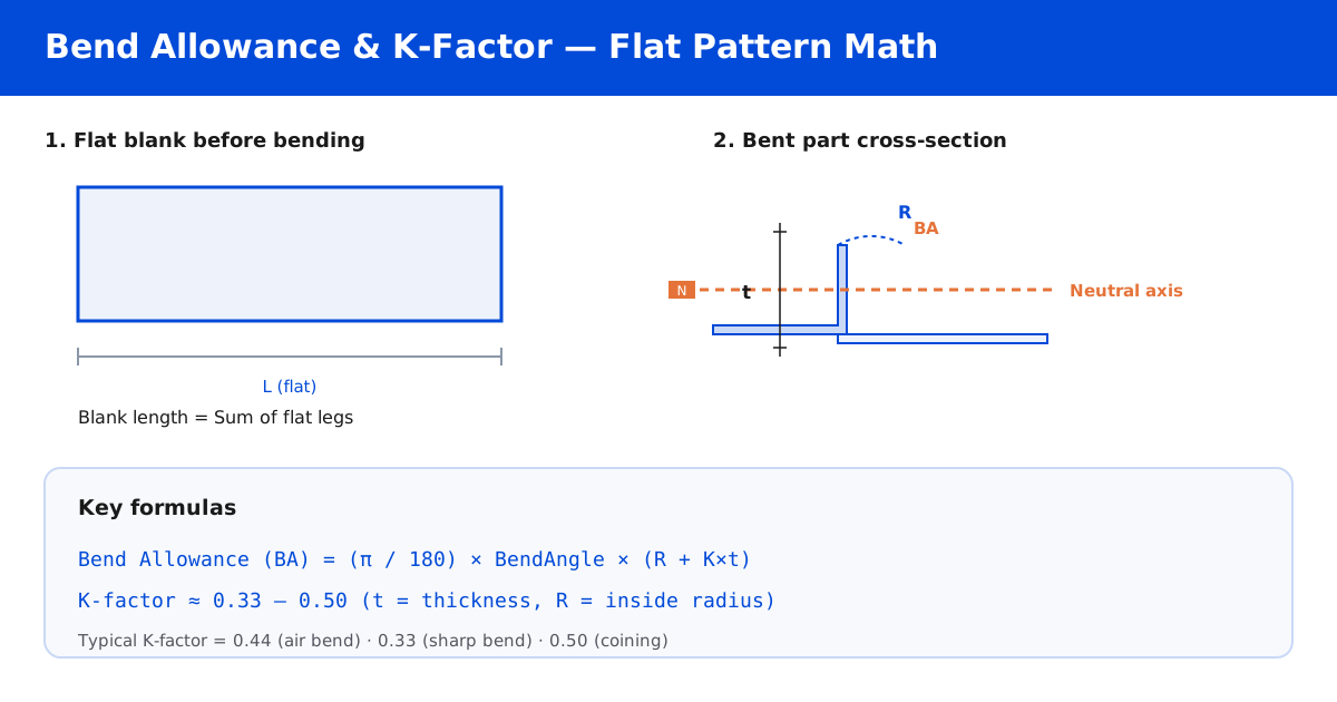
Metal does not stay the same length when you bend it. The outside of the bend stretches, and the inside compresses. In between there is a neutral axis — the layer that keeps its original length — and it is not in the middle of the sheet.
That is the whole concept: to get a correct flat pattern, you have to account for that neutral axis. If you just add up the length of the legs, your blank is wrong.
What is the neutral axis?
When a sheet is bent, the material on the inside of the radius is squeezed and the material on the outside is stretched. The plane where the material neither stretches nor compresses is the neutral axis.
In most sheet metal, the neutral axis sits at roughly 0.4 × t from the inside surface (where t is material thickness). The distance from the inside of the bend to the neutral axis, relative to the thickness, is the K-factor.
- K-factor = distance from inside surface to neutral axis ÷ material thickness
- Typical value: 0.33 to 0.50
- Common default for air bending: ~0.44 (some software uses 0.40)
The two numbers that matter
Fabricators and CAD software use two related but different values. Don’t mix them up.
Bend allowance (BA)
Bend allowance is the length of the arc of the neutral axis through the bend. It is what you add to your flat pattern.
BA = (π / 180) × BendAngle × (R + K × t)Where:
BendAngleis in degreesRis the inside bend radiusKis the K-factortis material thickness
Bend deduction (BD)
Bend deduction is the amount you subtract from the sum of the two outer legs. It gives the same answer as bend allowance, but it measures from the outside of the flanges instead of from the neutral axis.
The relationship is:
BD = 2 × (R + t) − BAThe most important rule: use one system consistently. If your CAD is set to bend deduction and you program the press brake in bend allowance, every part will be wrong by a consistent amount.
K-factor values you can use today
| Material | Typical K-factor |
|---|---|
| Mild / carbon steel, air bend | 0.44 |
| Stainless steel (springier) | 0.40 – 0.45 |
| Aluminium | 0.44 – 0.47 |
| Coining / bottoming | 0.33 |
| Sharp bend (R close to minimum) | 0.33 – 0.38 |
These are starting points. Real values shift with tooling, tonnage, and material batch. That is why you should always check against a known sample.
How to set the inside radius
The inside bend radius is the single biggest lever on bend allowance, and it is one you control. Practical guidelines for air bending (press brake, V-die):
- Minimum inside radius ≈ 1 × t for mild steel, 1.5 × t for stainless, 1 × t for aluminium
- A larger radius makes bending easier, prevents cracking, and improves tolerance
- A smaller radius saves space but increases tonnage and the risk of marks or cracking
Rule of thumb for the V-die opening
V-die opening ≈ 8 × t (fine for most jobs)For thicker plate, use more clearance: 10 × t is a safe start.
Worked example
Take a 3 mm mild-steel bracket that needs a 90° bend, a flat leg of 100 mm, and a return leg of 50 mm, using an inside radius of 4 mm and a K-factor of 0.44.
t = 3, R = 4, K = 0.44, BendAngle = 90°

BA = (π / 180) × 90 × (4 + 0.44 × 3)
   = 1.5708 × (4 + 1.32)
   = 1.5708 × 5.32
   = 8.36 mm
Flat length = 100 + 50 − 2 × (4 + 3) + 8.36 = 142.36 mm (approximately).
Note how the bend eats into the legs. If you had simply added 100 + 50 you would have made the part 7–8 mm too long and then had to fight it in the weld or assembly.
Six mistakes that throw your parts out of tolerance
- Mixing bend allowance and bend deduction between CAD and the press brake.
- Using the wrong K-factor for the material (stainless behaves very differently from mild steel).
- Forgetting that the radius changes with tooling — a different V-die gives a different radius.
- Ignoring springback on high-strength or hard alloys — you may need to over-bend.
- Treating a bent part like a machined part — bends drift more than laser-cut profiles.
- Not checking against a physical sample before committing to a full run.
Should you calculate it yourself or let the shop do it?
Honestly, you do not need to be a bend-allowance expert. A good fabricator runs the flat pattern through verified software and, more importantly, checks the first article. What you should do is:
- Specify the material and thickness clearly.
- Specify the inside bend radius you want (or let the shop choose and tell you).
- Ask whether your CAD and their press brake are using the same K-factor / method.
- Order a sample or first article before a large run.
FAQ
Does bend allowance change with bend angle?
Yes. It scales with the angle because a 90° bend sets up a much longer neutral-axis arc than a 20° bend.
What K-factor should I use if I’m not sure?
Start with 0.44 for mild steel and aluminium, and 0.42 for stainless. Then confirm against a sample. Accuracy beats elegance.
Can I bend right at the minimum radius?
You can, but expect more springback and more risk of marks. For clean, repeatable parts, add a little radius.
Related reading:
- How to Design for Sheet Metal Fabrication (DFM)
- Common Sheet Metal Design Mistakes
- Sheet Metal Tolerances: What You Can Actually Expect
Information is a starting point for your own verification. Tolerances, springback, and tooling all vary by machine and material. If you’d like an engineer to review your flat pattern before you cut metal, we are happy to help.