Common Sheet Metal Design Mistakes (and How to Fix Them)
Common Sheet Metal Design Mistakes (and How to Fix Them)
Most sheet metal problems aren’t machine problems — they’re design problems that were baked into the model before a single cut was made. The frustrating part is they’re almost all avoidable with a few simple rules.
Here are the design errors we see most often, what they do to your part, and the easy fix for each.
1. Sharp internal corners where bends or cuts meet
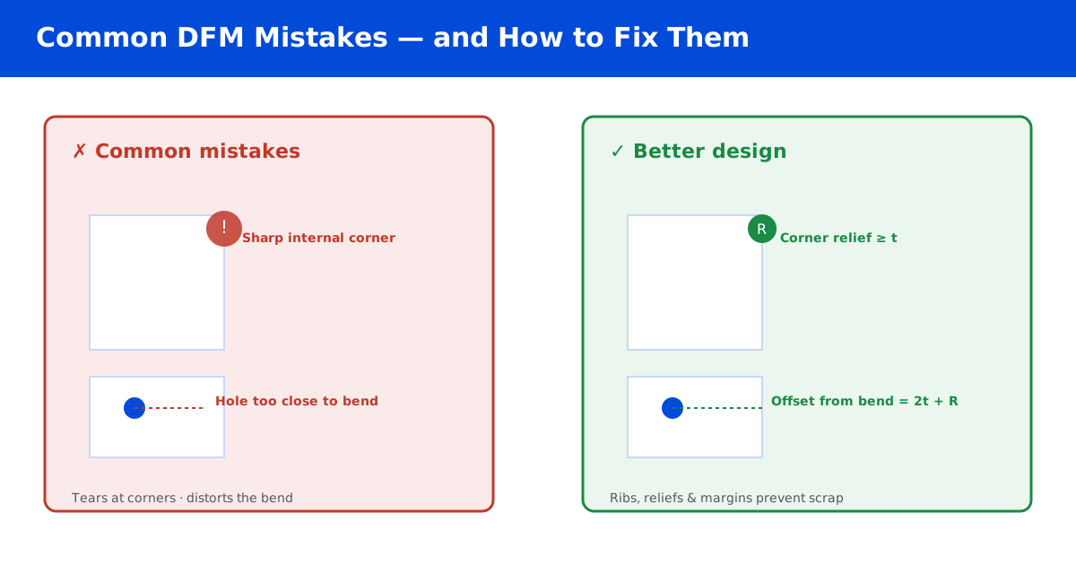
A 90° corner that’s sharp on the inside looks clean in CAD, but it doesn’t exist in real sheet metal. Without a corner relief, the material tears, the part cracks at the corner, and you get stress risers.
The fix: Add a small corner relief — a relief radius or slot roughly equal to the material thickness. This lets the bend happen cleanly and prevents tearing.
2. Holes too close to a bend line
A hole right next to a bend gets pulled out of it during forming, ending up oval or off-position. This ruins the hole for fastening.
The fix: Keep holes at least 1.5–2 × t away from the bend, or offset them to a flat area. If you must have a hole near a bend, put it in a relief.
3. Missing bend relief on long flanges
A long flange along an edge that ends at a corner needs a bend relief so the bend doesn’t crack into the adjacent wall.
The fix: Cut a relief slot at the end of the bend, typically just wider than the material thickness, with a small radius at the bottom.
4. Wall-to-wall ratios that cause buckling
If the bent wall is too short relative to the material thickness, the press brake can’t clamp it and the bend is unreliable.
The fix: Keep a minimum flange, typically ≥ 3–4 × t (and more for thick material), and give the die room.
5. Spotting embosses and dimples too close to edges
Formed features like embosses, dimples, and curled edges have their own clearance needs. Placing them too close to an edge causes distortion or tearing.
The fix: Leave enough flat material around each formed feature, and check the recommended minimum distance.
6. Deep bends that need too much tonnage
A bend with a very small radius on thick, hard material can exceed the press brake’s capacity or cause cracking on the outside.
The fix: Use a realistic inside radius for the material and thickness (see our bend-allowance guide). If you need a sharp corner, expect cost and cracking risk.
7. Adding tolerance to every feature
It’s tempting to call ±0.1 mm on everything “to be safe.” You won’t get cleaner parts — you’ll get a bigger quote and a lot of arguments.
The fix: Only tolerance the features that actually mate or align. Everything else gets a general tolerance.
8. Pockets and cutouts with sharp, unbounded corners
A long slot or cutout with a sharp corner at both ends creates stress risers and can tear during forming or brittle fatigue in service.
The fix: Radius every internal cutout corner — a small radius (often ≥ t) greatly improves strength and appearance.
9. Not checking the sheet direction (grain)
Sheet metal has a grain direction from rolling, and bends behave differently with and against the grain. This is especially important on aluminium and on parts that will be bent a lot.
The fix: Design bends so they’re not across the grain wherever you can, and check with your fabricator if the direction matters.
10. Specifying an impossible finish over an edge
A powder coat or anodize on a very thin, sharp edge will be thin or patchy at the radius. That “ghost line” at the bend is a real finishing effect, not a fault.
The fix: Either accept a rounded edge and the finish effect, or choose a finish that hides it. If the edge is cosmetic, radius it.
A quick self-check checklist
Run this before you send a file:
- Are there corner reliefs at every internal corner?
- Are holes at least 1.5–2 × t from the nearest bend?
- Is every long flange given a bend relief?
- Is the minimum flange ≥ 3–4 × t?
- Are embosses and dimples clear of edges?
- Is the inside bend radius realistic for the material?
- Are only functional features tight-toleranced?
- Are internal cutout corners radiused?
- Have I considered grain direction?
- Will the finish look OK at the edges?
FAQ
What’s the most expensive sheet metal design mistake?
Often it’s over-tolerancing combined with a feature the process can’t hold, which leads to scrap and rework. Under-tolerancing the mating features is a close second.
What’s a “bend relief”?
A small cutout at the point where a bend ends, which keeps the corner from tearing. It’s usually just wider than the material thickness with a small bottom radius.
Do I need corner reliefs?
Yes, if you have internal 90° corners where two bends or a bend and a cut meet. Without them, material tears at the corner.
Can a hole be right on a bend line?
Technically it can be placed, but it won’t stay round and will drift out of position. Keep holes in flat areas.
Related reading:
- How to Design for Sheet Metal Fabrication (DFM)
- Sheet Metal Bend Allowance & K-Factor
- Sheet Metal Tolerances: What You Can Actually Achieve
Most of these fixes take about a minute in CAD and save hours on the floor. If you’d like an engineer to give your drawing a quick DFM once-over, send it over — it’s the cheapest insurance you’ll buy.